Views: 0 Author: Site Editor Publish Time: 2026-08-25 Origin: Site


Modern vehicles are no longer purely mechanical machines. A mid tier sedan produced today carries over 150 distinct electrical connection points, while luxury models and electric vehicles routinely exceed 300. Every signal that travels through your car, from the throttle position sensor to the infotainment touchscreen, passes through some form of interconnect system. These components operate in one of the harshest environments any electronic hardware will ever encounter: temperature swings from minus 40 to plus 125 degrees Celsius, constant vibration, road salt spray, moisture ingress, and electromagnetic interference from dozens of onboard systems.
Yet connectors rarely get the attention they deserve. Engineers specify them as line items on a bill of materials, purchasing teams treat them as commodities, and end users never see them at all. The reality is that connector failure is one of the leading root causes of vehicle electrical warranty claims, and a single intermittent contact can trigger anything from a flickering dashboard light to a complete propulsion shutdown.
An automotive connector is a specialized electromechanical interface designed to establish and maintain reliable electrical circuits between wiring harnesses, electronic control units, sensors, actuators, and other subsystems within a vehicle, built to withstand extreme thermal cycling, mechanical vibration, chemical exposure, and moisture while delivering consistent signal and power transmission throughout the vehicle service life.
Understanding how these components are categorized, what standards govern them, and where they fit in real vehicle architectures gives engineers and procurement teams a practical edge. The choices made during the connector selection phase ripple through manufacturing yield, field reliability, and warranty cost for years. This guide walks through connector types, the engineering requirements that separate automotive grade parts from commercial alternatives, and the applications where each family excels. It also covers selection methodology, emerging technology trends, and answers questions that surface repeatedly during design reviews and supplier evaluations.

Table of Contents
Automotive connectors are purpose built electromechanical joints that link separate electrical circuits inside a vehicle, ensuring continuous signal and power flow under conditions that would destroy standard commercial grade interconnects within weeks of road use.
The fundamental difference between an interconnect designed for a consumer electronics device and one engineered for a car lies in the operating environment. A smartphone charging port lives in a controlled climate, sees modest mechanical stress, and gets replaced every two to three years. A connector inside a vehicle must survive a decade or more of daily thermal expansion cycles, road debris impact, humidity fluctuations between 5 and 95 percent, and vibration profiles that peak between 20 and 2000 Hz depending on engine mount proximity and suspension geometry.
The economic stakes are significant. Industry warranty data consistently shows that electrical system faults account for roughly 30 to 40 percent of all vehicle warranty claims, and within that category, connector and terminal issues represent the single largest subcategory. An intermittent contact on a CAN bus line can put a vehicle into limp mode, requiring a dealer visit. A corroded power terminal on a battery management system connector can trigger a thermal event. These are not theoretical risks. They are documented failure modes that cost automakers billions annually.
From an engineering perspective, the connector is the point where the idealized schematic meets physical reality. A wiring diagram shows clean lines connecting components, implying that current flows unimpeded. In practice, every connector introduces contact resistance, parasitic capacitance, potential galvanic corrosion, and a mechanical failure point. The art of automotive electrical system design is largely the art of managing these interfaces, and the consequences of getting it wrong extend far beyond a malfunctioning dome light.
A typical sealed inline connector used in an engine bay harness contains between 2 and 48 individual cavities. Each cavity houses a terminal that must be crimped to a specific wire gauge, seated into a housing with a retention lance that produces measurable retention force, and sealed against the environment using a combination of cavity plugs, interface seals, and possibly a connector body grommet. The terminal material is usually brass or bronze, plated with tin or sometimes gold for low voltage signal circuits, selected based on the current carrying requirement and the corrosion sensitivity of the contact pair.
The housing itself is typically made from glass filled nylon or polybutylene terephthalate, chosen for dimensional stability across the operating temperature range and resistance to automotive fluids. Locking mechanisms vary from simple finger latches to secondary locking devices that prevent terminal backout during vibration. Sealing strategies include radial seals at the interface, axial seals at the wire entry, and for particularly demanding environments, potting or overmolding that encases the entire connection in a solid polymer block.
Although organizations like the USCAR, LV214, and ISO 8092 publish standards that define connector performance classes, these standards establish minimum requirements, not equivalence. Two connectors that both meet USCAR 2 Class A may differ dramatically in insertion force curve, contact wipe geometry, and long term fretting behavior. This is why automakers maintain qualified parts lists and conduct extensive validation testing before approving a supplier for production. Selecting a connector based solely on its standard class designation without understanding the application specific nuances is a common and costly mistake that surfaces months after launch when field data begins accumulating.
The main types include sealed and unsealed inline connectors, header or board to wire connectors, power distribution connectors, coaxial and high speed data connectors, and specialty formats like fiber optic and hybrid power signal connectors, each engineered for a specific combination of current rating, environmental exposure, and signal integrity requirements.
Sealed inline connectors are the workhorse of vehicle electrical systems. They connect two wiring harness sections and are designed to operate in wet or dirty environments. The engine compartment, underbody, chassis, and exterior lighting circuits all rely on sealed inline families. These connectors achieve environmental protection through multi layer sealing: a peripheral seal between the mated halves, individual cavity seals around each wire, and in some designs a secondary rear seal on the wire entry side. The sealing performance is typically rated to IP67 or IP6K9K, meaning the connection can withstand immersion in one meter of water for 30 minutes and direct high pressure spray respectively.
Sealing Rating | Protection Level | Typical Application Zone |
|---|---|---|
IP67 | Temporary immersion, dust tight | Engine bay, exterior lighting |
IP6K9K | High pressure water jet, dust tight | Underbody, wheel well |
Unsealed (IP00) | No ingress protection | Cabin interior, dashboard |
IP68 | Continuous immersion | Submerged sensors, fuel system |
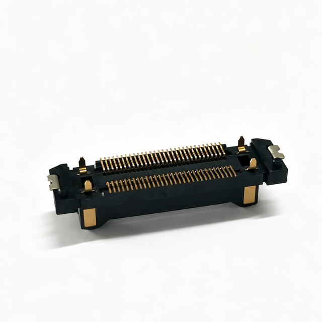
When a wiring harness meets a printed circuit board, the interface is handled by a PCB connector that solders or press fits onto the board and accepts the harness terminals on the other side. These connectors are found on every electronic control unit in the vehicle: the engine management ECU, transmission controller, body control module, infotainment head unit, and increasingly, the battery management systems in electric vehicles. The design challenges here differ from inline connectors because solder joint reliability, pin coplanarity, connector standoff height, and the thermal expansion mismatch between the FR4 substrate and the connector housing all influence long term reliability.
Board to wire connectors are also where signal density reaches its highest level. A modern body control module may use a 96 position connector carrying low current logic signals, CAN bus lines, and power feeds simultaneously. Managing crosstalk between adjacent pins and ensuring adequate contact normal force across all 96 positions within the available insertion force budget requires sophisticated terminal design and careful housing geometry optimization.
Power connectors handle high current loads ranging from 15 amps for auxiliary circuits to over 500 amps for battery to inverter links in electric vehicles. These connectors use larger terminals, often 1.5 to 16 square millimeter cross section wires, and employ features like busbar integration or bolted connections to manage thermal load. The contact area is significantly larger than signal terminals, and the materials may shift to copper alloys with silver plating for high current paths where tin plating alone cannot provide adequate corrosion resistance at elevated temperatures.
High voltage connectors for electric vehicle applications carry additional requirements. They must provide high voltage creepage and clearance distances, incorporate high voltage interlock circuits that signal the battery management system to disconnect before separation, and include electromagnetic shielding to contain the switching noise generated by the inverter. The orange housings used on these connectors are not merely a color convention. They are a safety standard that alerts service personnel to the presence of hazardous voltage.
Modern vehicles increasingly use Ethernet, FPD Link, GMSL, and other high speed protocols for camera, display, and sensor data. A vehicle connector designed for these applications must maintain controlled impedance, minimize insertion loss and return loss, and in many cases provide a fully shielded differential pair path from cable to board. The connector geometry, contact length, and dielectric properties all become critical parameters that determine whether the link achieves its target data rate and bit error ratio. At 10 Gbps, even a fraction of a millimeter of excess contact length can introduce reflections that degrade the signal beyond recovery.

Automotive connectors must meet stringent requirements across thermal endurance, vibration resistance, current carrying capacity, sealing performance, mechanical durability, and electromagnetic compatibility, validated through standardized test protocols defined by USCAR, LV214, JASO, and ISO specifications.
The operating temperature range for a connector depends on its installation location. Cabin interior connectors typically operate between minus 40 and plus 85 degrees Celsius. Engine bay and exterior connectors may see continuous exposure at 125 degrees Celsius with short excursions to 150 degrees. This thermal load drives material selection decisions: the housing resin must maintain flexural modulus, the terminal spring force must not relax due to stress relaxation in the contact alloy, and the sealing materials must remain elastic across the full range without taking a permanent compression set.
Thermal cycling is more destructive than steady state heat. A connector that operates continuously at 120 degrees may fail rapidly when subjected to 1000 cycles between minus 40 and plus 125 degrees, because differential thermal expansion between the terminal and housing causes fretting wear on the contact surface, degrading the contact interface and increasing resistance over time until the connection becomes intermittent.
Vibration profiles in vehicles vary by location. Engine mounted connectors experience broadband vibration from 20 to 2000 Hz with peak accelerations exceeding 10 g. Body mounted connectors see lower amplitudes but broader frequency content due to road input through the suspension. The connector locking mechanism must maintain full engagement under these conditions, and terminals must resist backout through primary retention lances and, in critical applications, secondary locking devices that engage after the terminal is fully seated.
Random vibration testing per ISO 16750 3 or USCAR 2 exposes connectors to accelerations and frequencies that simulate years of road use in a matter of hours. Connector designs that pass static retention force tests can still fail vibration testing if the resonance of the terminal within the cavity aligns with a dominant vehicle vibration frequency, which is why resonance frequency analysis during the design phase is essential.
Application | Current Range | Voltage Class | Terminal Size |
|---|---|---|---|
Signal and sensor circuits | 0.1 to 3 A | 12 to 48 V | 0.13 to 0.35 sq mm |
Body and lighting | 3 to 15 A | 12 to 48 V | 0.5 to 1.0 sq mm |
Power distribution | 15 to 60 A | 12 to 48 V | 1.5 to 6.0 sq mm |
High voltage EV systems | 50 to 500+ A | 400 to 800 V | 6.0 to 50 sq mm |
Current rating is not simply a function of wire gauge. The contact resistance at the terminal interface generates heat proportional to the square of the current. A connector rated for 15 amps carries a thermal margin that accounts for ambient temperature, neighboring current carrying circuits, and the thermal conductivity of the housing. Exceeding the rated current, even temporarily, can soften the housing resin and relax the terminal normal force, creating a degradation cycle that accelerates toward failure.
A waterproof connector used in exterior or underbody applications must maintain seal integrity not just at the time of manufacture but after years of thermal cycling and vibration. The sealing materials, typically silicone or EPDM, have finite service lives. Compression set, the tendency of an elastomer to permanently deform after sustained compression, reduces seal force over time. This is why accelerated aging tests that subject sealed connectors to 1000 or more thermal cycles are critical: they reveal whether the seal will maintain its function through the vehicle life or degrade to the point of allowing moisture ingress that corrodes the contact interface.
Every connector in a vehicle is potentially an antenna. Unshielded contacts can radiate switching noise from power electronics or pick up interference from external sources. Shielded connectors for high speed data links must provide 360 degree shielding continuity from the cable shield through the connector body to the board ground plane. Any gap in this shielding path, whether from a poorly designed shield termination or an incompletely mated connector, creates a slot antenna that can compromise the electromagnetic compliance of the entire vehicle and cause test failures that are notoriously difficult to trace back to the connector.

Automotive connectors appear in every major vehicle system, from powertrain management and body electronics to safety systems, infotainment networks, and electric vehicle powertrains, each application imposing a distinct combination of environmental, electrical, and packaging constraints.
The engine compartment is the most demanding environment for any electrical component. Connectors here attach to fuel injectors, ignition coils, crankshaft and camshaft position sensors, mass airflow sensors, and the engine control unit itself. They operate in continuous heat from the engine block, are splashed with road salt and engine oil, and experience vibration transmitted through the engine mounts.
Injector connectors, for example, must carry peak currents of 8 to 12 amps during the initial solenoid pull in phase, then drop to a holding current of approximately 1 amp. The connector must handle this current profile without contact degradation while withstanding direct contact with fuel vapor. Terminal plating on these connectors is often specified as tin over nickel, providing corrosion resistance and fretting mitigation that pure tin plating cannot match over the vehicle lifetime.
Body control modules manage lighting, wipers, door locks, windows, and climate controls. The connectors on these modules are typically unsealed for interior circuits and sealed for exterior runs. LED lighting has changed the connector landscape because older incandescent systems drew 2 to 5 amps per bulb, allowing some connector families to be shared across circuits. LED systems draw significantly less current but require more precise dimming control, which means connectors that once only needed to handle power now also carry pulse width modulated signals that are sensitive to contact resistance variation.
Safety critical systems demand the highest level of connector reliability. Airbag squib connectors use positive locking mechanisms with visual confirmation features, gold plated terminals for zero risk of fretting corrosion, and short circuit detection bars that bridge the firing circuit to prevent accidental deployment during connector mating or unmating. These connectors are never shared with other circuits and follow dedicated routing through the vehicle harness.
Advanced driver assistance systems add complexity. A modern ADAS suite may include six cameras, multiple radar units, and LiDAR, each requiring high speed data connectors with shielded differential pairs. The data rates on these links reach 8 Gbps per channel, and connector performance margins at these frequencies are measured in fractions of a decibel. A connector that degrades by 1 dB through vibration induced contact wear can cause link errors that disable an automated lane keeping function.
The electric vehicle revolution has created an entirely new category of high voltage, high current connector applications. The connections between the battery pack and the inverter, the inverter and the motor, the onboard charger and the AC inlet, and the DC fast charge port and the battery all require connectors rated for 400 to 800 volts and currents exceeding 300 amps.
These connectors incorporate multiple safety features beyond their current carrying capacity. The high voltage interlock loop, a low current signal circuit that runs through every high voltage connector in series, signals the battery management system to open the contactors if any connector is partially disengaged. This prevents arcing during disconnection under load, which could cause catastrophic damage to both the connector and the surrounding vehicle structure.
EV Connector Location | Typical Voltage | Typical Current | Key Safety Feature |
|---|---|---|---|
Battery to inverter | 400 to 800 V | 300 to 500 A | HVIL, shielding |
DC fast charge port | 400 to 800 V | 200 to 500 A | Temperature sensing |
Motor phase connections | 400 to 800 V | 400 to 600 A | Creepage clearance |
Auxiliary 12V loads | 12 V | 5 to 30 A | Fuse integration |
Selecting the right connector requires evaluating current and voltage requirements, environmental exposure level, available package space, mating cycle expectations, applicable regulatory standards, and total system cost including tooling, validation, and warranty risk, not merely matching a catalog specification to a circuit parameter.
Begin with the actual load profile, not the nominal rating. A circuit labeled as 5 amps may experience inrush currents of 15 amps for 50 milliseconds on startup. The connector must handle this transient without thermal damage. Determine the continuous current, the peak current, the duty cycle, and the ambient temperature at the installation location. These four parameters, combined, define the thermal envelope that the connector must survive, and underestimating any one of them can lead to field failures that would have been caught during proper load analysis.
Vehicle environments fall into roughly four zones with increasing severity: passenger cabin, trunk or rear cargo area, engine compartment, and exterior underbody. Each zone maps to a sealing requirement, a temperature range, and a vibration profile. Assigning the wrong environmental classification to a connector is a common error that surfaces as field failures months or years after launch, because the connector may pass initial validation but degrade rapidly under real world conditions it was never designed to handle.
Packaging constraints often override electrical considerations. A connector that electrically meets every requirement but does not fit in the available space is useless. In practice, engineers frequently must select a smaller connector family and accept reduced current margin or fewer cavities, then compensate through circuit design changes such as splitting a high current load across two circuits or relocating a module to create more connector access room. The packaging engineer and the electrical engineer must communicate early and often, because a connector that looks perfect on a schematic may be physically impossible to route in the actual vehicle body.
Once a candidate connector is identified, validate it against the applicable standard. If the vehicle program follows USCAR, confirm that the connector meets the correct performance class for the target zone. If the program follows LV214, verify the vibration and shock profile. Do not assume that meeting one standard automatically satisfies another. The test conditions differ, and connectors optimized for one standard may underperform when tested to a different one, particularly in sealing longevity and vibration endurance categories.
A connector that performs perfectly in validation testing can still cause problems in production. Terminal insertion force during harness assembly affects cycle time and worker fatigue. Mating force at the vehicle assembly plant can exceed ergonomic limits if the connector has too many cavities. Serviceability matters too: a connector buried behind the dashboard that requires three hours of disassembly to access will generate disproportionate warranty labor costs even if the connector itself is inexpensive. The total cost of ownership for a connector includes its purchase price, assembly time, validation cost, and projected warranty expense over the vehicle lifecycle.
The connector landscape is being reshaped by vehicle electrification, autonomous driving sensor suites, zonal electrical architectures, and the push toward lighter, smaller, and more thermally efficient interconnect solutions that can handle higher data rates and voltages in less space.
Traditional vehicle electrical architectures distribute electronic control units throughout the vehicle, with each function having its own controller connected via a central gateway. Zonal architecture consolidates controllers into regional domain controllers, with each zone aggregating the I/O from all sensors and actuators in its geographic area. This shift reduces wire length and vehicle weight but concentrates more circuits into fewer, larger connectors at the domain controller interface. The result is demand for high density connectors with 48 to 128 positions that combine power, signal, and high speed data in a single housing, creating new challenges in insertion force management and thermal loading.
Every gram matters in modern vehicle design, especially in electric vehicles where weight directly reduces range. Connector manufacturers are responding with terminal designs that maintain contact force in smaller footprints, housing materials with higher strength to weight ratios, and hybrid connectors that combine multiple circuit types in a single body to eliminate redundant housing material. The challenge with miniaturization is thermal management because smaller terminals have less surface area to dissipate contact resistance heat, and smaller housings provide less thermal isolation between adjacent current carrying circuits.
Advanced simulation tools now allow connector designers to model thermal behavior at the cavity level, identifying hot spots before tooling investment and enabling optimization of terminal geometry and housing rib structure to improve heat dissipation without increasing package size.
The transition from CAN and LIN protocols to automotive Ethernet and serializer deserializer links is driving a fundamental change in connector requirements. Where CAN bus could tolerate relatively simple unshielded connectors at 500 kbps, a 10GBASE T1 Ethernet link running at 10 Gbps demands precisely controlled impedance connectors with minimal pair to pair crosstalk and excellent shielding continuity. The connector is no longer just a mechanical interface. It is a microwave component that must be characterized using vector network analyzer measurements and eye diagram analysis, and connector vendors now publish scattering parameter models alongside traditional mechanical and electrical datasheets.
Regulatory pressure to reduce vehicle environmental impact is extending to connector materials. Halogen free housing resins, lead free and antimony free flame retardants, and recyclable terminal alloys are all entering production. The challenge is maintaining the mechanical and thermal performance that automotive applications demand while meeting increasingly restrictive material regulations across different global markets, and in some cases, material changes that improve sustainability can reduce performance margins in ways that require redesign of the terminal geometry to compensate.

A properly specified and validated connector is designed to last the full vehicle service life, typically 10 to 15 years or 150,000 to 250,000 kilometers, without failure. However, service life depends heavily on the operating environment and whether the connector was correctly specified for its installation zone. Connectors exposed to temperatures or vibration levels beyond their rated envelope will degrade faster.
Check the connector datasheet for compliance with recognized automotive standards such as USCAR 2, USCAR 3, LV214, or ISO 8092. The datasheet should specify the performance class, temperature range, vibration profile, and sealing rating. Request validation test reports from the supplier, and verify that the testing was conducted by an accredited laboratory using the current revision of the applicable standard.
The three leading causes of field connector failures are moisture ingress due to seal degradation, fretting corrosion caused by micro motion at the contact interface, and terminal backout during vibration. All three are preventable through proper connector selection, correct crimp tooling and process control, and the use of secondary locking devices where specified.
Using commercial grade connectors in vehicle applications is strongly discouraged. Commercial connectors lack the thermal range, vibration resistance, and sealing required for automotive environments. Even in cabin interior applications where conditions are milder, the vibration and temperature cycling profiles exceed what commercial connectors are designed to handle, leading to premature failure.
IP67 indicates protection against dust ingress and temporary immersion in water up to one meter deep for 30 minutes. IP6K9K is an automotive specific extension that adds protection against high pressure water jets at elevated temperature, simulating conditions like pressure washing or driving through heavy rain at speed. For exterior and underbody automotive applications, IP6K9K is the appropriate target.
Electric and hybrid vehicles introduce high voltage and high current connector requirements that conventional vehicles do not have. Battery to inverter connections, motor phase connections, and charging interfaces require connectors rated for 400 to 800 volts and currents up to several hundred amps. These connectors must incorporate high voltage interlock circuits, electromagnetic shielding, and creepage and clearance distances that standard automotive connectors do not provide.