Views: 0 Author: Site Editor Publish Time: 2026-07-17 Origin: Site


Table of Contents
AI workloads and PCIe Gen 5/Gen 6 architectures demand high bandwidth. These requirements push traditional PCB trace lengths and edge connectors past their physical signal integrity limits. Modern server motherboards face severe physical constraints. Engineers struggle with limited real estate, thermal throttling, and airflow obstruction while trying to route high-speed signals. The conflict between high internal data throughput needs—such as CPU to GPU or NVMe arrays—and physical board limitations requires a new approach.
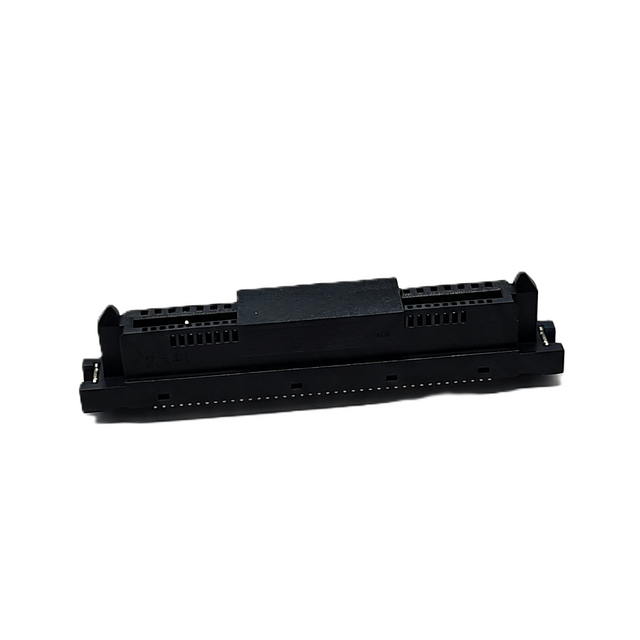
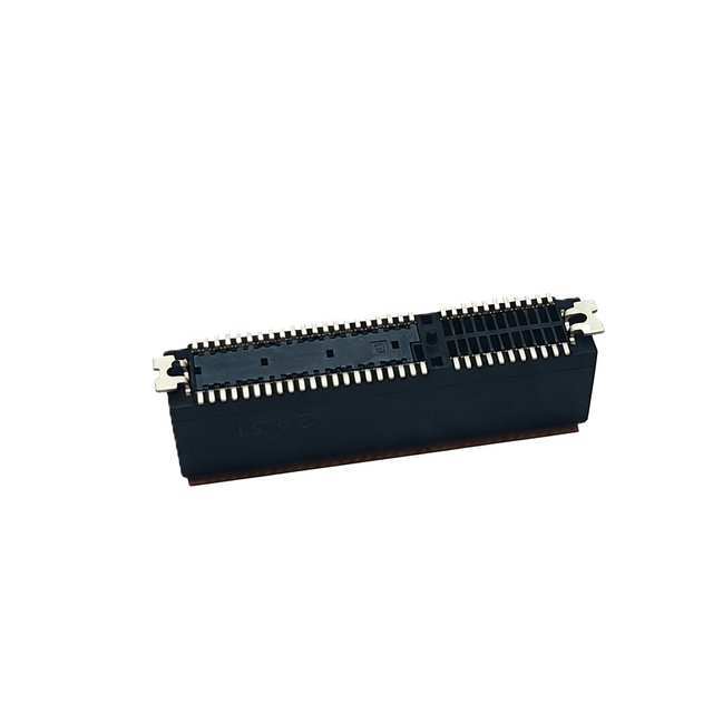
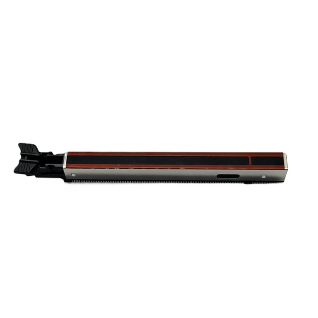
The MCIO connector solves this core engineering problem. Originally developed by industry leaders like Amphenol and Molex, the Mini Cool Edge IO serves as the standard solution for high-density, low-latency internal wiring. It shifts high-speed signals off the lossy motherboard and into optimized cable assemblies. This guide explores the technical architecture, implementation risks, and critical applications of this interconnect technology.
Standardized Performance: MCIO connectors adhere to the SNIA SFF-TA-1016 specification, enabling reliable PCIe Gen 5 (32 GT/s) and Gen 6 (64 GT/s) signal transmission over longer distances than standard PCB traces.
Space and Thermal Efficiency: The slim, card-edge-like form factor drastically reduces PCB footprint while improving chassis airflow compared to traditional PCIe slots and older SAS/SATA connectors.
Architectural Flexibility: Multiple mechanical orientations (straight, right-angle, side-exit) and breakout capabilities (e.g., x8 to dual x4) allow system architects to decouple storage and accelerators from the motherboard.
Implementation Reality: Successful integration requires strict evaluation of cable bend radii, mating cycle durability, and vendor-specific signal loss tolerances.
Routing PCIe Gen 5 and Gen 6 signals through standard FR4 PCB materials introduces severe signal attenuation. High-frequency signals degrade rapidly over distances greater than a few inches. System architects previously relied on expensive, low-loss PCB materials or active retimers to push signals across large server boards. These methods increase manufacturing complexity and power consumption. When we design high-density systems, relying solely on PCB traces becomes a significant liability.
Legacy internal interconnects struggle to meet modern density and bandwidth requirements. We have seen firsthand how older standards fail in high-performance environments. The limitations are physical and electrical. Standard PCIe edge slots consume significant physical real estate. They block critical airflow paths necessary for cooling high-TDP processors. Older connectors also feature bulky mechanical profiles that complicate routing in dense 1U and 2U chassis designs.
Here are the primary reasons legacy connectors fail in modern AI servers:
Signal Degradation: Older interfaces cannot handle the 32 GT/s or 64 GT/s speeds without excessive insertion loss.
Physical Bulk: Traditional slots block airflow, causing thermal throttling on adjacent components.
Routing Inflexibility: Rigid board-to-board connections force suboptimal component placement.
Density Limits: Legacy headers take up too much board space, limiting the number of NVMe drives or accelerators a single board can support.
The MCIO connector provides a highly efficient over-the-board cabling solution. It functions as a compact card-edge interface that bypasses lossy PCB traces entirely. Engineers route high-speed signals through shielded twinax cables directly from the processor region to peripheral endpoints. This approach preserves signal integrity, reduces board layer counts, and simplifies overall motherboard design.
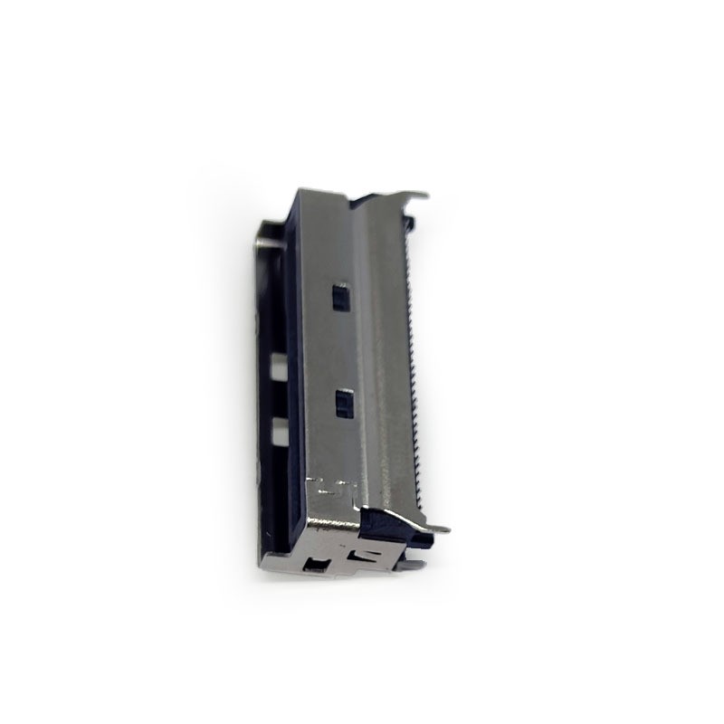
The SNIA SFF-TA-1016 specification governs the mechanical and electrical parameters of the Mini Cool Edge IO interface. This standard ensures interoperability across the enterprise hardware ecosystem. Hardware developers can confidently mix and match cables and headers from different certified manufacturers. The specification defines strict insertion loss budgets, crosstalk limits, and mechanical mating requirements for high-speed operation.
Pin configurations determine the lane support and bandwidth capacity of the interface. The standard defines several form factors to accommodate different lane counts. System designers select the appropriate pin count based on the specific peripheral bandwidth requirement. We use these variations daily to optimize board layouts.
Pin Count | PCIe Lane Support | Typical Application | Bandwidth (Gen 5) |
|---|---|---|---|
38-Pin | x4 Lanes | Single NVMe Drive, Dedicated NIC | 16 GB/s |
74-Pin | x8 Lanes | Dual NVMe Drives, Mid-tier Accelerators | 32 GB/s |
124-Pin | x16 Lanes | High-End GPUs, PCIe Switch Uplinks | 64 GB/s |
Spatial adaptability remains a primary advantage of this technology. We rely on different connector orientations to solve specific packaging problems. Straight connectors work best for vertical direct-attach cabling in spacious chassis environments. Right-angle connectors minimize vertical clearance. Side-exit or lateral connectors allow low-profile routing parallel to the motherboard. These low-profile options are essential for high-density AI servers where vertical space is severely restricted.
While engineers primarily utilize these connectors for PCIe signaling, the physical interface remains protocol-agnostic. The same hardware supports SAS, SATA, CXL (Compute Express Link), and high-speed Ethernet protocols. This versatility allows hardware designers to standardize on a single connector family for multiple storage and networking topologies. You can streamline your bill of materials by standardizing on one interface type.
Signal integrity at Gen 5 and Gen 6 speeds dictates interconnect choices. An MCIO connector paired with a high-quality twinax cable assembly exhibits significantly lower insertion loss than a traditional PCIe riser or a long motherboard trace. Twinax cables isolate signals effectively, reducing crosstalk and electromagnetic interference. This isolation allows signals to travel further without requiring active amplification.
Replacing bulky, rigid PCIe slots with low-profile headers saves significant amounts of PCB real estate. A traditional x16 PCIe slot consumes a large footprint and dictates the mechanical layout of expansion cards. Flexible cable headers allow engineers to place the connection point anywhere on the board. This flexibility frees up space for additional memory channels, power delivery components, or specialized cooling hardware.
Feature | Traditional PCIe Slot | MCIO Cable Assembly |
|---|---|---|
Signal Reach (Gen 5) | Very limited (requires retimers) | Extended (up to 1 meter passive) |
Board Footprint | Large, rigid placement | Minimal, flexible placement |
Airflow Impact | High obstruction | Low obstruction (routable) |
Vibration Tolerance | Moderate (cards can unseat) | High (positive latching) |
Latency considerations play a critical role in AI cluster design. Moving from direct-attach PCB traces to high-speed twinax cable assemblies introduces negligible latency. The propagation delay through a copper twinax cable is extremely low. The signal integrity benefits often outweigh any microscopic latency additions. Cleaner signals require fewer retransmissions and lower error correction overhead, ultimately improving effective system latency.
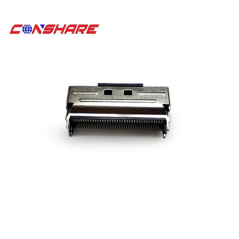
Modern AI architectures require direct, high-bandwidth connections between host processors and dedicated accelerators. Cables facilitate these CPU-to-GPU topologies without relying on complex, costly PCIe switch chips. Engineers route x16 connections directly from the CPU socket area to custom GPU baseboards. This direct-attach method maximizes throughput and minimizes architectural bottlenecks. We see this topology in almost every modern training cluster.
High-density NVMe storage backplanes rely heavily on these compact interfaces. Front-panel NVMe arrays require significant lane counts routed from the motherboard to the drive cages. The slim profile of the connector maximizes storage density. It enables efficient hot-swap backplane designs in tightly packed rack configurations. Cables route cleanly along the chassis side walls, avoiding central airflow paths.
SmartNIC and DPU integration demands high-throughput, low-profile interfaces. Network controllers must connect directly to the processing core to minimize data handling overhead. The compact headers fit easily near the CPU socket. They provide the necessary x8 or x16 bandwidth for 400G and 800G Ethernet adapters without occupying standard PCIe expansion slots.
Breakout cable configurations maximize port utilization and design flexibility. System designers frequently split lanes to connect multiple devices. A single x8 motherboard header can route to dual x4 PCIe endpoints using a breakout cable. This bifurcation strategy allows a single high-density port to serve multiple NVMe drives or smaller peripheral devices, optimizing motherboard trace routing.
Routing thick bundles of high-speed twinax cables impacts internal chassis airflow. While removing large PCIe slots improves general airflow, dense cable bundles can create new thermal shadows. Engineers must carefully plan cable paths to avoid blocking airflow behind high-TDP processors or memory banks. Strategic cable management and custom routing channels mitigate these thermal risks.
Physical limitations of twinax cables dictate routing constraints. Tight bends in high-speed lines cause impedance mismatches. These mismatches lead to signal reflection, signal degradation, and packet loss. Engineers must adhere strictly to the manufacturer's specified minimum bend radius. Chassis layouts must accommodate gentle cable curves rather than sharp 90-degree angles.
To successfully implement these connectors, follow these field-tested steps:
Calculate Lane Requirements: Map out exact PCIe lane needs for all GPUs, NVMe drives, and NICs.
Determine Cable Lengths: Measure physical routing paths, accounting for bend radii and avoiding heat sinks.
Select Wire Gauge: Choose the appropriate AWG based on the required length and signal speed (e.g., 30 AWG for short runs, 28 AWG for longer runs).
Verify Latching: Ensure the chosen connectors feature robust mechanical latches to withstand shipping vibration.
Test Signal Integrity: Request and review S-parameter data from the cable manufacturer before finalizing the design.
Mechanical durability requires careful evaluation during the design phase. Development environments subject connectors to frequent plugging and unplugging. Engineers must evaluate the mating cycle rating of the connector latches, shell materials, and gold contacts. Production servers rarely see frequent mating cycles, but the initial connection must remain secure under vibration and thermal expansion stress.
Signal integrity guarantees separate premium cable manufacturers from low-tier suppliers. Engineers must request comprehensive S-parameter data from vendors. Insertion loss profiles and eye diagram test results verify Gen 5 or Gen 6 compliance. Relying on basic continuity testing is insufficient for 64 GT/s signaling. Verifiable test data ensures the cable assembly will perform reliably in the final system.
Compatibility and interoperability testing prevent costly manufacturing delays. Sourcing from reputable suppliers ensures strict compliance with SFF-TA-1016 standards. Certified tier-1 partners guarantee mechanical compatibility across different hardware platforms. Non-compliant vendors may introduce proprietary latching mechanisms or incorrect pinouts, leading to vendor lock-in or hardware damage.
Choosing between custom and standard cable lengths impacts project timelines. Ordering custom-length runs optimizes internal cable routing and minimizes excess slack. However, custom lengths increase lead times and unit costs. Designing chassis layouts around standard off-the-shelf assemblies reduces procurement complexity. Engineers must balance the aerodynamic benefits of exact-length cables against supply chain realities.
As AI servers and PCIe Gen 5/Gen 6 platforms continue to demand higher bandwidth and greater system density, selecting the right MCIO connector has become essential for maintaining signal integrity, improving airflow, and enabling flexible internal system architecture. By carefully evaluating connector specifications, cable routing, mechanical reliability, and compatibility, engineers can build scalable, high-performance server platforms that are ready for future technology upgrades.
Working with an experienced connectivity solutions provider is equally important for ensuring consistent quality and long-term reliability. CONSHAREA offers a comprehensive range of high-performance MCIO connectors and cable assemblies for AI servers, storage systems, and high-speed networking applications. With advanced engineering, strict quality control, and professional technical support, we help customers optimize signal performance, simplify server design, and accelerate next-generation computing deployments.
Audit your current server chassis schematics to identify airflow bottlenecks caused by legacy PCIe slots.
Calculate the exact PCIe lane counts required for your next-generation accelerator and NVMe topologies.
Request technical drawings, S-parameter data, and physical samples from qualified interconnect manufacturers.
Perform mechanical fit testing using standard off-the-shelf cable lengths before committing to custom runs.
A: MCIO supports higher bandwidth capacities, specifically designed for PCIe Gen 5 (32 GT/s) and Gen 6 (64 GT/s) signal integrity. It features a smaller physical footprint and better crosstalk isolation compared to older SlimSAS connectors, which were primarily designed for slower SAS and early PCIe generations.
A: Yes. The connector is protocol-agnostic. Since CXL operates over the physical layer of PCIe, these connectors fully support CXL topologies, providing the low-latency, high-bandwidth physical pathways required for memory expansion and accelerator caching.
A: Maximum cable length depends on the wire gauge (AWG) and the signal speed. For PCIe Gen 5 using typical 30 AWG twinax, reliable passive transmission usually maxes out around 0.5 to 1 meter. Longer distances require active retimers to maintain signal integrity.
A: A breakout cable utilizes lane bifurcation. It splits a larger lane configuration into multiple smaller ones. For example, it can physically route a single x8 host port connection into two separate x4 endpoint connectors, allowing one host port to drive two distinct NVMe SSDs.
A: Connectors come in straight, right-angle, and side-exit (lateral) orientations. Straight headers suit vertical direct-attach setups. Right-angle and side-exit headers minimize vertical height, making them ideal for low-profile routing in dense 1U or 2U server chassis.
A: The physical connector itself does not dictate hot-swap capability. Hot-plugging depends entirely on the specific host controller, the endpoint device, and the operating system implementation. While the pins can handle the electrical connection, the system must support PCIe hot-plug events.
A: SFF-TA-1016 is the technical specification published by SNIA (Storage Networking Industry Association). It standardizes the mechanical dimensions, pinouts, and electrical performance requirements for the Mini Cool Edge IO interface, ensuring interoperability between different manufacturers.