Views: 0 Author: Site Editor Publish Time: 2026-07-30 Origin: Site


Selecting the right connector for an electrical or electronic system is one of the most consequential decisions an engineer makes during the design phase. Connectors serve as the critical interface between subsystems, carrying power, signal, or data across PCBs, enclosures, and field wiring boundaries. A poorly chosen connector can introduce signal degradation, mechanical failure, or safety hazards that ripple through the entire product lifecycle.
The right connector reliably matches your application's electrical requirements, fits within the mechanical and spatial constraints of your design, withstands the environmental conditions it will encounter, complies with relevant industry standards, and delivers acceptable total cost of ownership over the product's expected service life. Selection should begin with a thorough requirements analysis covering current rating, voltage rating, contact resistance, mating cycle expectations, termination method, and environmental sealing.
This guide walks through every major dimension of connector selection, from foundational electrical and mechanical parameters to environmental hardening, regulatory considerations, and long term reliability planning. By following a systematic approach rather than relying on catalog browsing, teams can avoid costly redesigns and field failures.
Table of Contents

An electrical connector is an electromechanical device that joins electrical conductors to create a continuous circuit path that can be engaged and disengaged as needed, and understanding its core components and operating principles is essential for making informed selection decisions.
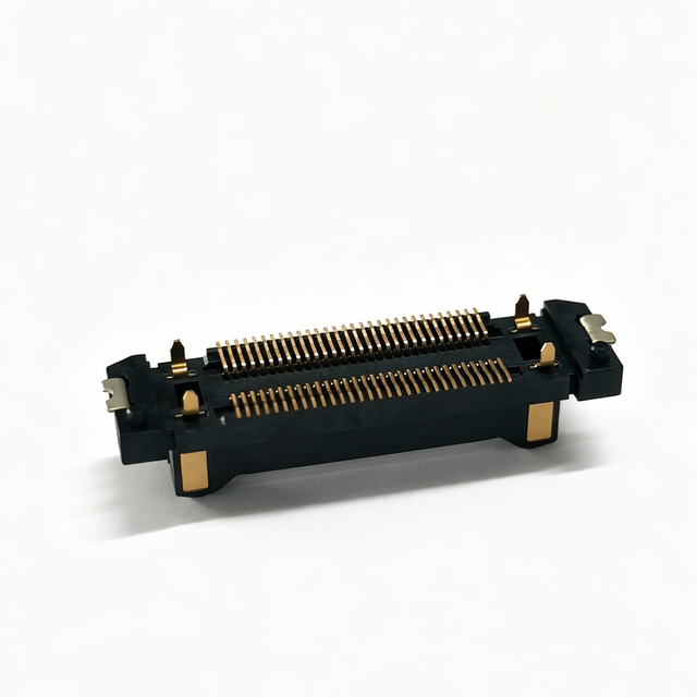
At its most basic level, a connector consists of two mating halves: a plug side and a receptacle side. Each half contains contacts that are typically stamped from copper alloy and plated with gold, tin, or other conductive materials. The contacts are housed within an insulator body, usually made from thermoplastic or thermoset materials, which provides electrical isolation between adjacent contacts and mechanical alignment during mating. A contact retention mechanism, such as a locking lance, secures each contact within the housing to prevent backout during vibration or thermal cycling.
Beyond the basic plug and receptacle architecture, engineers must understand several functional classifications. Signal connectors prioritize high speed transmission with controlled impedance and minimal crosstalk, while power connectors are designed to carry higher currents with low contact resistance and robust thermal management. Hybrid connectors combine both signal and power contacts within a single housing, reducing connector count and simplifying assembly in space constrained designs. Board-to-board connectors serve PCB interconnects with fine pitch, wire-to-board connectors bridge cables to printed circuits, and wire-to-wire connectors join cable segments in harness assemblies.
The performance of any connector is ultimately determined by the quality of the contact interface. When two contacts mate, they form a gas tight connection through the deformation of microscopic surface asperities, creating a conductive pathway. This interface is maintained by the normal force exerted by the contact spring, typically measured in grams. Higher normal force generally means lower contact resistance and better reliability, but also increases insertion and withdrawal forces. Contact plating plays a decisive role in long term performance: gold plating offers excellent corrosion resistance for low level signal applications, while tin plating is more economical but susceptible to fretting corrosion if the connection experiences micro motion.
Connector selection requires systematic evaluation of electrical specifications, mechanical parameters, environmental ratings, regulatory compliance, and economic factors, with each criterion weighted according to the specific demands of the target application.
The selection process should begin with a comprehensive requirements matrix that captures every parameter the connector must satisfy. Electrical requirements typically include current rating per contact, voltage rating, contact resistance, insulation resistance, dielectric withstanding voltage, and any high speed parameters such as impedance or crosstalk specifications. Mechanical requirements include contact pitch, number of positions, mating and unmating force, engagement length, and overall package dimensions. Environmental requirements encompass operating temperature range, IP rating, vibration and shock resistance, and resistance to specific chemicals.
Once the requirements matrix is established, engineers can evaluate candidate connectors against each criterion. It is important to recognize that manufacturer datasheets present specifications under standardized test conditions that may not reflect real world operating scenarios. Derating is a critical practice: current carrying capacity should be derated for elevated ambient temperatures, for high altitude installations, and for connectors enclosed in sealed housings with limited airflow. The following table summarizes the most critical electrical parameters:
Parameter | Definition | Selection Guidance |
|---|---|---|
Current Rating | Maximum continuous current without exceeding rated temperature rise | Apply 20 to 30 percent derating margin. Consider ambient temperature and airflow. |
Voltage Rating | Maximum voltage the connector can safely withstand | Verify operating and transient voltage levels. Derate for altitude. |
Contact Resistance | Total resistance at the contact interface | Lower is better for power. Monitor stability over cycling for signal applications. |
Insulation Resistance | Resistance between electrically isolated contacts | Should exceed 1000 megohms in most applications. |
Dielectric Withstanding Voltage | Voltage withstandable for one minute without breakdown | Should provide at least 2 times margin above maximum operating voltage. |
Mechanical fit is often the factor that eliminates otherwise suitable candidates. The available PCB footprint, panel cutout dimensions, cable bend radius, and enclosure interior volume all impose hard constraints. Engineers should use 3D CAD models to verify that the selected connector fits without interfering with adjacent components or cable routing. Mating and unmating force is another critical parameter, particularly for connectors with 50 or more positions, where cumulative friction can make manual engagement impractical without assistive features such as screw locks or cam actuation.
The method by which wires or PCBs attach to contacts affects both assembly cost and long term reliability. Common termination methods include solder, crimp, press fit, IDC, and spring clamp. Crimp termination offers excellent reliability and field repairability but demands precise tooling. Press fit enables solderless PCB attachment but requires careful hole tolerance control. IDC and spring clamp terminations enable rapid assembly but may have limitations in high vibration applications.

Different connector families are engineered to serve distinct application domains, and matching the connector architecture to the intended use case is fundamental to achieving reliable system performance over the product lifecycle.
Power connectors are designed to carry currents ranging from a few amperes to several hundred amperes. Key design considerations include contact geometry for low resistance, thermal management to dissipate resistive heating, and safety features such as keyed housings and first mate last break contacts that ensure ground connections are established before power contacts. Blade and box terminal designs dominate lower current applications, while high current connectors often employ cylindrical pin and socket contacts with larger cross sections.
Signal connectors span an enormous range, from simple low pin count headers to high density backplane connectors carrying 25 Gbps or faster differential signals. For high speed digital applications, controlled impedance, minimal skew between differential pairs, and crosstalk management become paramount. Shielded connector systems with integrated ground planes are often required to meet emission limits and maintain signal integrity. For analog and sensor applications, low contact resistance and stable insulation resistance are the primary concerns.
RF connectors maintain controlled impedance across the mating interface to minimize reflections and signal loss at radio frequencies. Impedance is typically 50 ohms for most RF applications or 75 ohms for video and telecommunications. The following list highlights key RF connector categories:
Subminiature connectors for precision measurement and high density applications, supporting frequencies from DC to 18 GHz or higher
Standard bayonet and threaded connectors for general purpose RF applications up to 4 GHz, providing quick mating or robust environmental sealing
Precision connectors for laboratory and metrology applications requiring the highest measurement accuracy
Industrial connectors are built to survive harsh factory environments with vibration, dust, moisture, and chemical exposure. They feature robust metal or reinforced thermoplastic housings, threaded coupling mechanisms, and multi contact inserts that can carry power, signal, and pneumatic lines. IP67 or IP68 sealing is common. Automotive connectors must meet stringent requirements for vibration resistance, temperature cycling from minus 40 to plus 125 degrees Celsius, and resistance to automotive fluids. Sealed connector systems with silicone gaskets prevent moisture ingress, while positive locking mechanisms ensure connectors remain mated despite continuous vibration.
The operating environment dictates which connector materials, sealing strategies, and mechanical features are necessary, and environmental requirements should be treated as primary selection criteria rather than afterthoughts.
Environmental factors are among the most common causes of premature connector failure. Temperature extremes cause differential thermal expansion between contacts and housings, potentially leading to contact drift and increased resistance. Humidity and condensation can create electrolytic corrosion at the contact interface. Dust and particulate contamination can prevent proper contact engagement or create resistive films on contact surfaces. Chemical exposure from industrial processes or cleaning agents can degrade housing materials and contact platings.
Ingress protection ratings, defined by IEC standard 60529, provide a systematic way to evaluate sealing performance. The IP code uses two digits: the first indicates protection against solid objects and dust, the second against water. An IP54 rated connector is dust protected and splash resistant. An IP67 rated connector is dust tight and can withstand temporary immersion. Engineers should verify that the IP rating applies to both mated and unmated conditions, as some connectors achieve their sealing rating only when fully engaged.
Vibration and mechanical shock are critical in automotive, aerospace, rail, and heavy industrial applications. Connectors respond to vibration through several failure mechanisms: contact fretting causes progressive wear of the contact plating, leading to increased resistance and eventual open circuits. Contact bounce during shock events can cause momentary signal interruptions. The following strategies help mitigate vibration related failures:
Select connectors with contact normal forces above 100 grams
Choose connector systems with positive locking mechanisms
Use contact lubricants where recommended by the manufacturer
Provide strain relief and cable support to minimize mechanical load
Verify vibration test data covers the specific frequency spectrum of the application
Connector operating temperature range must encompass not only the ambient environment but also the temperature rise generated by current flowing through the contacts. High temperature applications near engines or furnaces require connectors with high temperature thermoplastic housings. Housing materials such as PBT, nylon, or PPS provide varying levels of chemical resistance, and engineers should consult compatibility data from material suppliers to verify suitability for all chemicals present in the operating environment.
Engineers frequently encounter a predictable set of pitfalls during connector selection, and awareness of these common errors can prevent costly design revisions, qualification delays, and field reliability problems.
One of the most pervasive mistakes is selecting a connector based solely on its published current and voltage ratings without applying appropriate derating margins. A connector rated for 10 amperes at 25 degrees Celsius ambient may only safely carry 6 to 7 amperes at 70 degrees Celsius. Responsible design practice requires derating current by at least 20 to 30 percent and verifying performance under worst case thermal conditions. Another frequent error is neglecting the cumulative effect of contact resistance in multi position connectors. While individual contact resistance of a few milliohms seems negligible, a 100 position connector carrying 5 amperes per contact dissipates significant power that can raise housing temperature and accelerate material aging.
Insertion force scales roughly linearly with contact count and normal force. A 200 position connector with 100 grams normal force per contact requires 20 kilograms of insertion force to fully mate. Without assistive mechanisms, this force is beyond what an operator can comfortably apply, leading to incomplete engagement, bent contacts, or damaged housings. Designers should calculate expected mating force early and specify screw locks or levers when force exceeds approximately 5 kilograms.
Connector discontinuation is a significant risk for products with long manufacturing lifecycles. A connector selected today may be obsoleted in three to five years if it serves a consumer electronics market with rapid product turnover. For industrial, medical, or aerospace products with 10 to 20 year lifecycles, engineers should prioritize connectors that are part of long term availability programs or that comply with industry standard footprints enabling second source procurement. Underestimating assembly and service complexity is another common pitfall: blind mating situations require connectors with guidance features and tactile feedback, while field serviceability demands connectors that can be repeatedly mated without specialized tooling.
Proper installation practices and ongoing maintenance protocols are essential for realizing the full reliability potential of any connector system, and even the best selected connector will underperform if installed or maintained incorrectly.
Installation begins with proper contact preparation. For crimp contacts, the correct crimp tool and die set must be used with the specified wire gauge. An improperly crimped contact may appear mechanically secure but exhibit high resistance due to insufficient wire compression. For solder contacts, proper solder temperature, dwell time, and flux selection are critical. Press fit contacts require controlled insertion force and verification that pins have fully seated without causing barrel deformation. During assembly, connectors should be mated with attention to alignment. Misaligned mating can damage contact beams, score contact platings, and deform housings. After mating, locking mechanisms should be fully engaged and verified.
Cable strain relief is one of the most important yet frequently neglected aspects of connector installation. Without adequate strain relief, cable weight, flexing, and handling loads transfer directly to the contact termination, leading to wire fatigue and eventual failure. Strain relief should be provided at the connector backshell through cable clamps, grommets, or molded boots. Cable routing should avoid sharp bends that exceed the minimum bend radius, and cables should be secured at regular intervals to prevent unsupported spans that can resonate during vibration.
Regular inspection and maintenance significantly extend connector service life. The following table outlines recommended maintenance activities:
Maintenance Activity | Recommended Frequency | Purpose |
|---|---|---|
Visual inspection of mated connectors | Quarterly, monthly in harsh environments | Check for housing damage or corrosion |
Contact cleaning | Annually or as needed | Remove dust and contamination from contact surfaces |
Mating cycle verification | During scheduled outages | Confirm smooth mating without excessive force |
Contact resistance measurement | Annually for critical paths | Detect gradual resistance increase |
Seal and gasket inspection | Biannually for sealed connectors | Verify O rings remain intact and elastic |
Connectors have finite service lives. Contact platings wear, contact springs fatigue, and housing materials embrittle over time, particularly under thermal cycling. For critical applications, establishing a proactive replacement schedule based on mating cycle count or operating hours can prevent unplanned failures. In safety critical systems, connectors should be replaced well before their expected failure point. Maintaining detailed documentation of part numbers, lot codes, and maintenance history enables root cause analysis when failures occur and supports predictive maintenance strategies.

Selecting the right connector is a multidisciplinary engineering challenge that demands careful attention to electrical, mechanical, environmental, and lifecycle considerations. By starting with a comprehensive requirements analysis, systematically evaluating candidate connectors, and applying appropriate derating margins, engineering teams can identify connectors that deliver reliable performance throughout the product lifecycle. Avoiding common pitfalls such as inadequate derating, neglecting mating force, and overlooking supply chain longevity further increases the probability of long term success.
Connectors may represent a small percentage of total product cost, but they serve as the critical junction points upon which entire system functionality depends. At CONSHARE, we understand that treating connector selection with the engineering rigor it deserves is a hallmark of well designed, reliable electronic products that perform consistently in demanding environments.
Electrical specs (current, voltage, contact resistance), mechanical fit (pitch, position count, mating force), environmental conditions (temperature, IP rating, vibration), and regulatory compliance. Build a requirements matrix, weight each criterion by your application, and evaluate candidates with derating margins applied.
Derating means operating below maximum rated specs to account for real-world conditions. A connector rated 10A at 25°C may only handle 6–7A at 70°C. Apply at least 20–30% derating to current ratings to prevent overheating and premature failure.
Power connectors handle higher currents with low contact resistance and thermal management. Signal connectors prioritize transmission integrity—controlled impedance, minimal crosstalk, and shielding for high-speed data. Hybrid connectors combine both in one housing for space-constrained designs.
IP54 for indoor dust and splash protection. IP67 for outdoor or industrial use with temporary immersion. IP68 for continuous submersion. Always verify the rating applies to both mated and unmated conditions—some connectors seal only when fully engaged.
Skipping derating margins, ignoring cumulative mating force on high-pin-count connectors, overlooking long-term supply availability, and underestimating assembly complexity. Neglecting contact resistance in multi-position connectors is another frequent cause of thermal issues discovered late in testing.