Views: 0 Author: Connector Expert Publish Time: 2026-07-17 Origin: Site


Table of Contents
While CPUs and GPUs dominate data center discussions, the physical hardware interface remains the critical bottleneck for system performance. These components directly impact signal integrity, thermal efficiency, and overall operating costs. As enterprise workloads push toward 400G and 800G data rates, legacy interconnects fail to support required bandwidths. This failure leads to unacceptable insertion loss, severe thermal throttling, and massive operational inefficiencies. Selecting the right server connector requires moving beyond basic compatibility. Hardware engineers must evaluate form factors, mating cycles, thermal profiles, and Multi-Source Agreement (MSA) compliance to ensure system stability. This guide provides a strict framework for evaluating and specifying hardware interfaces for modern server architectures.
Bandwidth vs. Signal Integrity: Upgrading to PCIe Gen 5/6 and 400G+ Ethernet requires connectors engineered for minimal crosstalk and insertion loss.
Thermal Management is Non-Negotiable: High-density I/O connectors (like QSFP-DD and OSFP) introduce significant heat; evaluating their heatsink integration and airflow impact is critical for system stability.
Copper vs. Fiber Trade-offs: Direct Attach Copper (DAC) remains superior for short-reach, low-power applications, while fiber-optic connectors are mandatory for high-bandwidth, long-reach data center scaling.
Standardization Reduces Risk: Prioritizing MSA-compliant connectors ensures multi-vendor interoperability, protecting supply chains and reducing vendor lock-in.
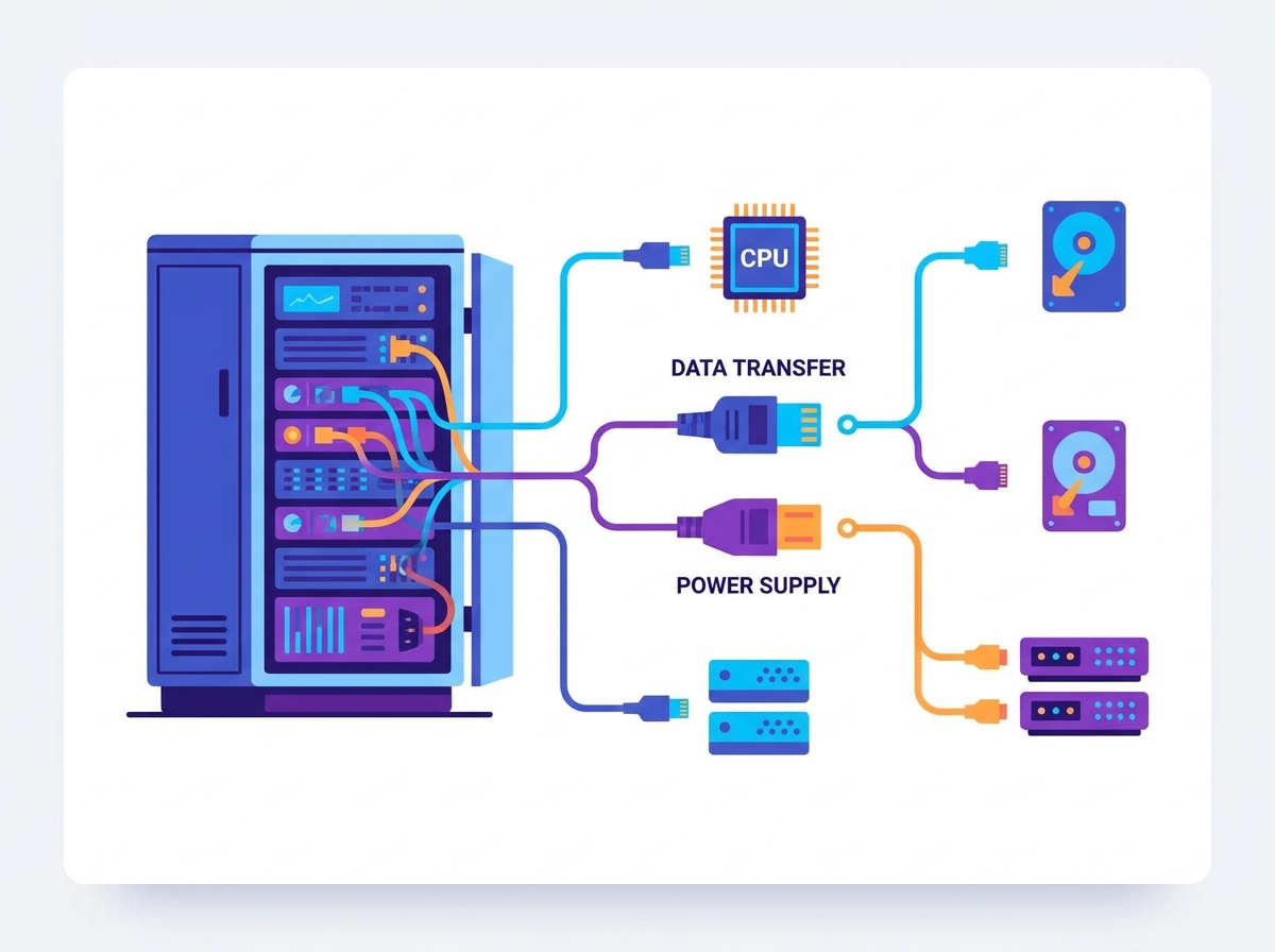
Modern server chassis require distinct interface types to handle internal component routing, external data transfer, and power delivery without creating physical or thermal bottlenecks. Understanding the specific function of each category is the first step in hardware specification. You have to look at the physical constraints of the motherboard, the airflow pathways, and the mechanical stress points where cables terminate.
Internal routing for blade servers, motherboard-to-daughtercard links, and modular architectures relies heavily on specialized high-speed interfaces. These components facilitate communication between compute nodes, storage arrays, and switch fabrics within the same chassis or midplane. When you are building a high-density compute node, the internal routing defines the maximum throughput of the system.
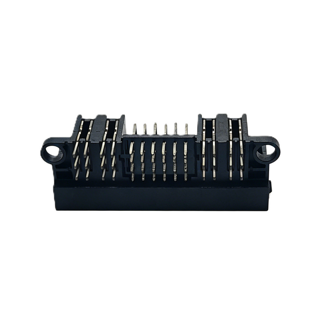
Key interface types include MCIO (Mini Cool Edge IO), SlimSAS, and high-density orthogonal backplane connectors like the Amphenol Paladin or TE STRADA Whisper. When evaluating these components, engineers must focus on pin density, orthogonal routing capabilities, and co-planar alignments. Support for high-speed differential signaling, specifically PCIe Gen 5, PCIe Gen 6, and PAM4 112G, is mandatory for modern compute environments. Failure to specify adequate internal connectors results in immediate data bottlenecks between the CPU and storage arrays.
Internal Connector Type | Primary Application | Max Supported Bandwidth | Key Mechanical Feature |
|---|---|---|---|
MCIO (Mini Cool Edge IO) | PCIe Gen 5/6 Routing | 64 GT/s per lane | Low profile, high pin density |
SlimSAS | Storage / NVMe linking | 24G SAS / PCIe Gen 4 | Flexible ribbon cable routing |
Orthogonal Backplane | Switch fabric to compute | 112G PAM4 | Direct right-angle mating |
Mezzanine (High-Density) | Motherboard to Accelerator | 112G PAM4 | Stack height variability |
Orthogonal backplane designs eliminate the traditional midplane PCB entirely. By allowing line cards and switch fabric cards to mate directly at 90-degree angles, you remove an entire layer of trace routing. This drastically reduces insertion loss. When working with 112G PAM4 signals, every millimeter of PCB trace degrades the signal. Direct orthogonal mating is often the only way to maintain signal integrity across a large chassis.
External data transfer bridges the server to the wider data center network. These interfaces must handle high data throughput while maintaining backward compatibility where necessary. They are primarily used for switch-to-server and server-to-storage networking in high-density rack setups. The physical port on the front or rear of the server dictates what kind of network topology you can deploy.
Common interface types range from legacy RJ45 for 1G/10G copper connections to SFP28 for 25G links. High-performance environments utilize QSFP28 for 100G and QSFP-DD or OSFP for 400G and 800G throughput. Evaluation must center on port density, physical footprint, and integrated thermal dissipation. High-speed transceivers generate substantial heat, making the connector's ability to interface with chassis airflow a primary design consideration.
When you plug an 800G OSFP module into a server, that single module can draw upwards of 20 to 30 watts. If the cage assembly on the motherboard lacks proper riding heatsinks or if the chassis fans cannot push enough CFM (Cubic Feet per Minute) through that specific zone, the optical module will overheat and shut down. You must specify cages with integrated thermal management.
Fiber-optic interfaces provide direct coupling of optical transceivers and active optical cables (AOCs) to physical fiber plants. They are essential for ultra-high-bandwidth backbone and leaf-spine clustering in modern data centers. Unlike copper, fiber relies on the physical alignment of microscopic glass cores.
Standard patch cabling often uses LC Duplex interfaces, while high-density breakout connections require MPO/MTP formats. Emerging high-density designs increasingly rely on SN or CS connectors. When selecting these components, insertion loss is the primary metric. Additionally, dust and contamination resistance, physical alignment precision, and fiber-count density dictate long-term reliability. Even microscopic misalignment in a fiber interface will cause severe signal degradation.
LC Duplex: The standard for 10G to 100G single-lane or dual-lane optics. Reliable, easy to clean, but takes up significant faceplate space.
MPO/MTP: Multi-fiber push-on connectors handle 8, 12, 16, or 24 fibers in a single housing. Essential for parallel optics (like 400G SR8), but highly susceptible to dust. One dirty fiber core ruins the entire link.
SN/CS Connectors: Very Small Form Factor (VSFF) connectors designed specifically for QSFP-DD and OSFP transceivers. They allow you to break out a 400G port into four independent 100G LC-equivalent connections directly at the transceiver faceplate.
Interfacing motherboards with RAM modules, NVMe solid-state drives, and high-speed expansion cards requires robust physical slots capable of handling continuous data streams. These components are heavily utilized in high-frequency trading or AI training rigs requiring maximum internal throughput. The mechanical retention force of these slots is critical, especially in environments subject to vibration.
Key interface types include DDR5 DIMM slots, PCIe CEM slots, and EDSFF (Enterprise & Datacenter Storage Form Factor) variants like E1.S, E1.L, and E3. Legacy U.2/U.3 slots remain common but are phasing out in high-performance environments. Evaluation focuses on compliance with the latest hardware standards, mechanical footprint, and structural robustness. Storage servers, in particular, require connectors rated for high mating cycles to accommodate frequent NVMe hot-swapping.
EDSFF is rapidly becoming the standard because it solves the thermal and signal integrity issues inherent in the older U.2 form factor. An E1.S drive can be placed vertically across the front of a 1U server, allowing for high storage density while leaving enough physical space between the drives for cool air to pass through to the CPUs behind them.
Delivering stable, high-current power from the Power Supply Unit (PSU) or busbars to the motherboard, GPUs, and peripherals is a foundational requirement. Power delivery must be efficient and safe, minimizing voltage drops and thermal output. A poorly specified power terminal will literally melt under the sustained load of modern AI accelerators.
Modern setups utilize OCP Open Rack busbar connectors, PCIe 5.0 12VHPWR or 12V-2x6 interfaces, and standard ATX/EPS power formats. Engineers must evaluate the current rating per contact, contact resistance, and mating safety features such as thermal sensing pins. Low-profile designs are also necessary to minimize airflow obstruction within densely packed chassis.
Selecting a server connector based solely on spec-sheet bandwidth ignores the physical realities of modern data center environments. True evaluation must encompass electrical, mechanical, and thermal dimensions to ensure long-term operational stability. You have to test these components under load, in the actual chassis, with the actual cooling configuration.
High-speed transmission requires strict impedance control. Hardware must be evaluated based on return loss, insertion loss, and crosstalk metrics (NEXT/FEXT) at target frequencies, such as 28 GHz or 56 GHz PAM4. Poor signal integrity necessitates higher power consumption for signal retiming and forward error correction (FEC). This inefficiency drives up operational costs and introduces excessive system latency.
When routing PCIe Gen 5 signals, the margin for error is virtually zero. The channel loss budget is strictly defined. If the physical interface introduces too much impedance mismatch, the signal eye diagram closes, and the receiver cannot distinguish between a 1 and a 0. This forces the system to rely heavily on FEC, which adds latency. In high-frequency trading or real-time AI inference, that latency is unacceptable for the application.
High-density I/O interfaces and optical transceivers generate localized heat. Designers must evaluate integrated riding heatsinks, thermal interface materials (TIMs), and the physical footprint relative to chassis airflow. Components that block critical airflow paths or fail to dissipate heat will cause adjacent optical transceivers or silicon chips to thermally throttle. This thermal degradation directly impacts server uptime and hardware lifespan.
You must look at the fin pitch and height of the heatsinks integrated into the I/O cages. If the fins are too close together, the static pressure required to push air through them exceeds what standard server fans can provide. The air will simply bypass the heatsink, flowing around it instead of through it, leading to rapid thermal runaway.
Balancing the physical pitch and depth of interfaces maximizes the number of ports per Rack Unit (RU) against the limits of cable routing. Over-densification without adequate structural planning leads to unmanageable cable bulk. This bulk blocks exhaust vents and creates high-risk mechanical strain during installation and maintenance operations.
If you pack thirty-two 400G QSFP-DD ports into a 1U switch or server faceplate, you have to consider the physical reality of routing thirty-two thick DAC cables or fiber trunks. The weight of those cables pulling down on the ports can cause mechanical failure of the cage solder joints on the motherboard. Proper cable management arms and strain relief mechanisms are mandatory.
Assessing the structural lifespan and contact wear of the pins is critical. A component rated for 50 mating cycles will fail rapidly in a testbed environment compared to one rated for 250 cycles. Choosing low-durability hardware results in premature contact wear, intermittent electrical continuity failures, and unscheduled downtime. This is particularly vital for storage servers requiring frequent drive replacements.
Gold plating thickness on the contact pins directly correlates to mating cycle durability. Standard commercial interfaces might use 15 microinches of gold, which is fine for a component plugged in once and left for five years. For hot-swappable NVMe bays, you need 30 microinches or more to survive the constant abrasion of insertion and removal.
Minimizing contact resistance, measured in milliohms, across power-delivery terminals reduces unnecessary voltage drops. Lower contact resistance decreases the amount of heat generated directly at the interface. This enhances overall power efficiency and reduces the data center cooling load, allowing for denser compute configurations.
When pushing 600 watts through a single PCIe 12VHPWR cable to a GPU, even a fraction of an ohm of resistance at the terminal creates significant localized heating. This is why proper crimping techniques, high-conductivity copper alloys, and secure latching mechanisms are heavily scrutinized during the hardware validation phase.
The transition from copper to optical interfaces is not absolute. Both mediums serve distinct, complementary roles across different architectural layers of the data center. Selecting the right medium depends entirely on distance, bandwidth, and power constraints. You do not run fiber where copper can reach, and you do not stretch copper beyond its physical limits.
Feature | Direct Attach Copper (DAC) | Active Optical Cables (AOC) / Fiber |
|---|---|---|
Latency | Ultra-low (No conversion) | Slightly higher (O-E-O conversion) |
Power Consumption | Near-zero | Higher (Transceiver power required) |
Reach / Distance | Short (Typically < 3 meters for 400G) | Long (Up to kilometers) |
Cable Flexibility | Rigid, heavy, can block airflow | Lightweight, flexible, improves airflow |
EMI Immunity | Susceptible to interference | Completely immune |
Common formats include SFP56 DAC, QSFP-DD DAC, and standard RJ45 Category cabling. DAC provides the lowest latency because it requires no optical-to-electrical conversion. It also features near-zero power consumption and is highly cost-effective for short distances. However, DAC is strictly limited by transmission distance, typically maxing out under 3 meters for 400G applications. The rigid and heavy cabling profile can also block exhaust paths. DAC is best utilized for intra-rack connections, particularly Top-of-Rack (ToR) switch-to-server links.
When deploying DAC at 400G, the wire gauge (AWG) becomes a major factor. To hit 3 meters, you often need 26 AWG wire, which is extremely thick and difficult to bend. If you force a tight bend radius to close a rack door, you will alter the impedance of the twinax cable inside, causing immediate signal degradation and link drops.
Optical setups commonly use LC Duplex and MPO/MTP formats terminating multi-mode or single-mode transceivers. Fiber offers complete immunity to electromagnetic interference (EMI) and supports high bandwidth over long distances. The lightweight cables significantly improve rack airflow. The primary drawbacks are higher initial procurement costs and increased power consumption at the transceiver level. Fiber is mandatory for inter-rack routing, spine-leaf architectures, and long-haul data center interconnects.
AOCs are a great middle ground. They have the optical transceivers permanently attached to the fiber cable. This eliminates the exposed optical interface, meaning you do not have to worry about dust contamination during installation. You just plug the ends into the server and the switch, and the link comes up. However, if the cable gets damaged, you have to replace the entire assembly, including the expensive transceivers.
Selecting the right server connector is essential for achieving reliable data transmission, efficient thermal management, and long-term system scalability. By carefully evaluating bandwidth requirements, signal integrity, connector durability, power delivery, and compatibility, businesses can build high-performance server infrastructure that supports modern data centers, cloud computing, AI workloads, and enterprise networking.
Working with an experienced connectivity solutions provider is equally important for ensuring long-term reliability and product quality. CONSHAREA offers a wide range of high-performance server connectors designed for modern computing environments. With advanced engineering, strict quality control, and comprehensive technical support, we help customers optimize system connectivity, improve signal performance, and build reliable, future-ready server and networking solutions.
Audit your current rack architecture to identify thermal bottlenecks caused by legacy high-density copper cabling blocking exhaust vents.
Specify MSA-compliant hardware for all upcoming server deployments to guarantee multi-vendor interoperability and secure your supply chain.
Transition to EDSFF storage interfaces for new NVMe deployments to maximize internal bandwidth and improve chassis airflow efficiency.
Implement strict mating cycle tracking for storage servers and testbeds to prevent unexpected contact wear failures during routine maintenance.
Standardize on specific wire gauges and bend radius limits for all DAC deployments to prevent physical damage and signal degradation.
A: QSFP-DD doubles the number of high-speed electrical interfaces compared to QSFP28. This allows it to support 400G and 800G data rates while remaining backward compatible with legacy QSFP optical modules and copper cables.
A: High contact resistance causes voltage drops across the connection, turning electrical energy into heat. This reduces the efficiency of power delivery to components like GPUs and increases the cooling requirements for the chassis.
A: EDSFF provides superior signal integrity for PCIe Gen 5 and Gen 6. It also offers better thermal dissipation and allows for higher drive density per rack unit compared to the older U.2 form factor.
A: It is generally not recommended for high-speed data rates. At 400G and above, DAC cables are limited to lengths of about 3 meters due to signal degradation, making them suitable only for intra-rack or Top-of-Rack connections.
A: Multi-Source Agreement (MSA) compliance ensures that transceivers and connectors from different manufacturers adhere to standardized physical and electrical specifications. This guarantees interoperability and prevents vendor lock-in.